

Autodesk RVT_ELEC_01101 - Autodesk Certified Professional in Revit for Electrical Design
Refer to exhibits.
(The image Is presented in Imperial units: 1 In = 25 mm (Metric units rounded].)
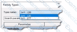
An electrical designer creates a lighting fixture family with the following types and then saves the family.
Refer to the exhibit.
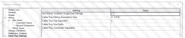
An electrical designer models a cable tray in a project and decides to check the box (or Use Annot. Scale tor Single Line Fittings and change the Cable Tray Fitting Annotation Size to 1/8" (3 mm).
What is the result?
(The image is presented m Imperial units: 1 In = 25 mm (Metric units rounded].)
Refer to exhibit.
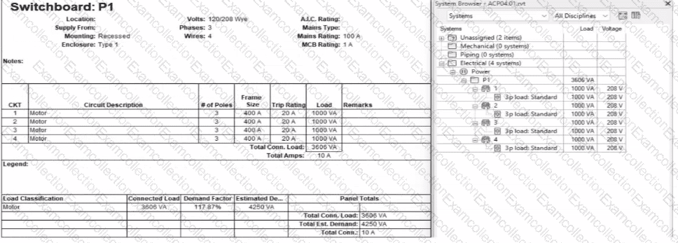
An electrical designer expects the total connected load on the switchboard to be 4000VA. but Revit Indicates a total connected load of 3606VA. What Is the cause of the discrepancy?
Refer to exhibits.
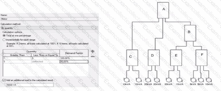
What is the demand load on Panel B?
Refer to exhibit.
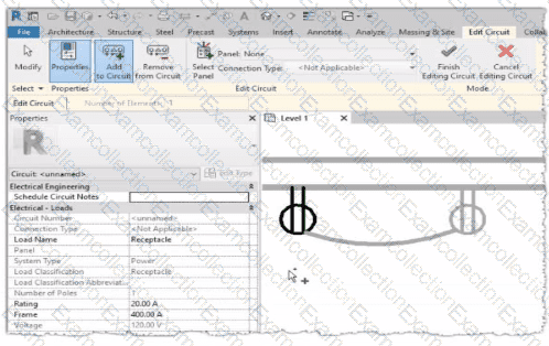
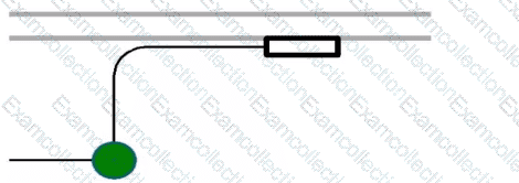
Why is one receptacle shown in full color (black) and one receptacle shown in halftone (gray)?
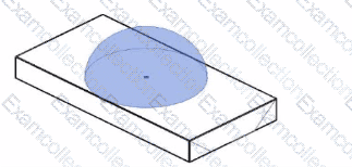
Refer to the exhibit.
Refer to exhibit.
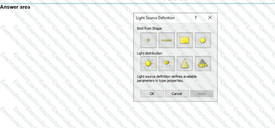
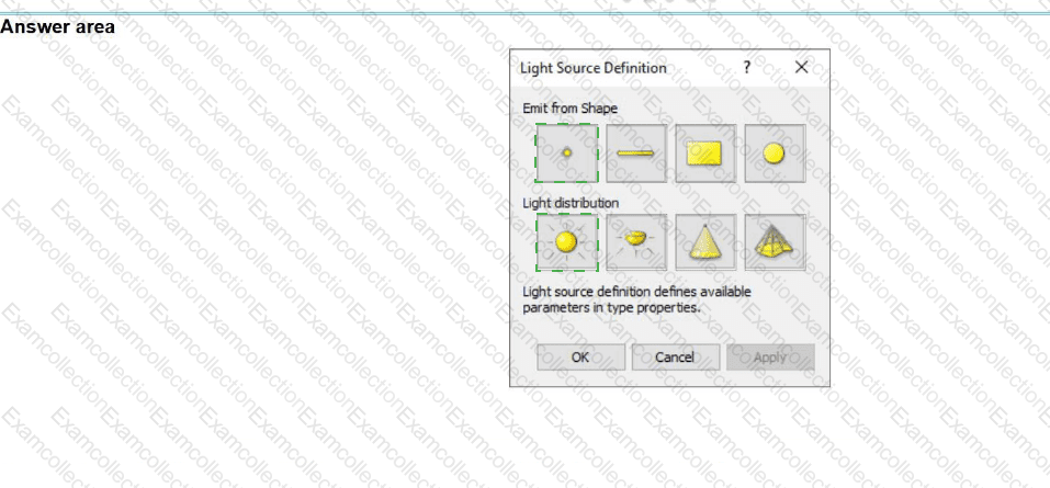
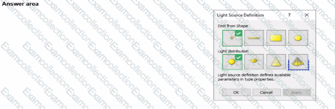
The exhibit is a lighting fixture family in the Family Editor environment and the light source is selected.
An electrical designer has downloaded a photometric web tile in IES format from a manufacturer's website for use within this lighting fixture family.
Define the light source's Emit Shape and Light Distribution for use with the photometric web (IES) file. (Select two in the answer area.)
Refer to exhibit.
(The Image is presented in Imperial units: 1 In = 25 mm [Metric units rounded).)

What is the electrical designer trying to do as shown in the exhibit?