

Autodesk RVT_ELEC_01101 - Autodesk Certified Professional in Revit for Electrical Design
Refer to exhibit.
(The image is presented in Imperial units: 1 In = 25 mm (Metric units rounded).)
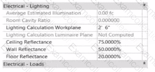
In the space properties for the space, the Lighting Calculation Luminaire Plane is Not Computed. What is causing this issue?
Refer to exhibit.
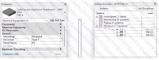
To which panel Is Panel P4 circuited?
Refer to exhibit.
(The image is presented in Imperial units: 1 In = 25 mm [Metric units rounded].)

An electrical designer is trying to add the selected three-way switch to the existing switch system "b". The designer is unable to add the switch to the switch system.
Why is this problem occurring?
Refer to exhibit.
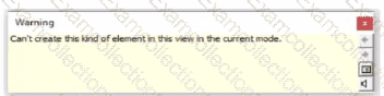
An electrical designer tries to place a generic annotation family in a data device family. The designer receives the error message as shown. What should the designer do?
An electrical designer is routing conduit through a building model to coordinate with other disciplines, the electrical designer wants to view selected components in a cropped 3D view.
With the conduit components selected, which tool should the designer use?
Refer to exhibit.
A panelboard has the following properties:
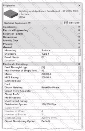
The Circuit Naming Scheme PanelSlolPhase. which defines the value of the Circuit Number parameter, is configured as follows:
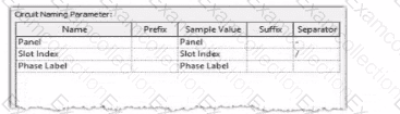
In electrical settings. Phase Labels have not been modified from the default "A." "B." and "C-
The Circuit Number lot a single-pole circuit in the panelboard's first breaker position is----------(Enter the correct value into the field)
An electrical designer needs to check for Interferences between conduit in the host model and beams in a linked structure model in the Interference Check dialog, select the items that the designer must select to perform the interference check. (Select two.)
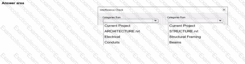
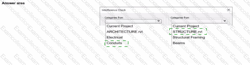

Refer to exhibit.
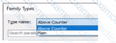
A family in a project contains the following types:
The following edits are made in the Family Editor and loaded into the project:
1. The type Plain is renamed to Standard
2 A new type is added named GFCI
Which types does this family now have in the project?
1. The type Plain is renamed to Standard
An electrical designer is working in a workshared project with a team of people. The electrical designer does not want to see the linked architectural model in any of their views. The rest of the team still needs to see the architectural link.
Which process should the electrical designer use?
Refer to exhibits.
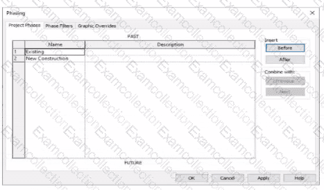
An electrical designer models an existing receptacle on an existing wall that the architect has indicated to be demolished.
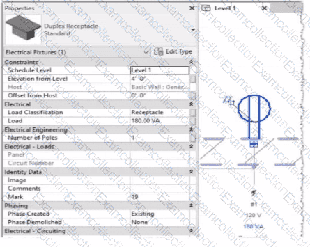
The view is intended to show demolition, and the view's Phase is set to New Construction. How should the designer indicate that the receptacle must also be demolished?